Problem Statement
Nuclear Magnetic Resonance (NMR) is a method of material analysis that is currently costly and inaccurate. Mass Spectrometry is far preferred for its ability to analyze a material. However, Mass Spectrometry is time intensive and destructive to the material being sampled. Covid-19 showcased a use case for a faster method of material analysis. This project aimed to create fully designed architecture of a full, portable, low-cost NMR system based on the digitization on an existing analog NMR device.
Starting Point
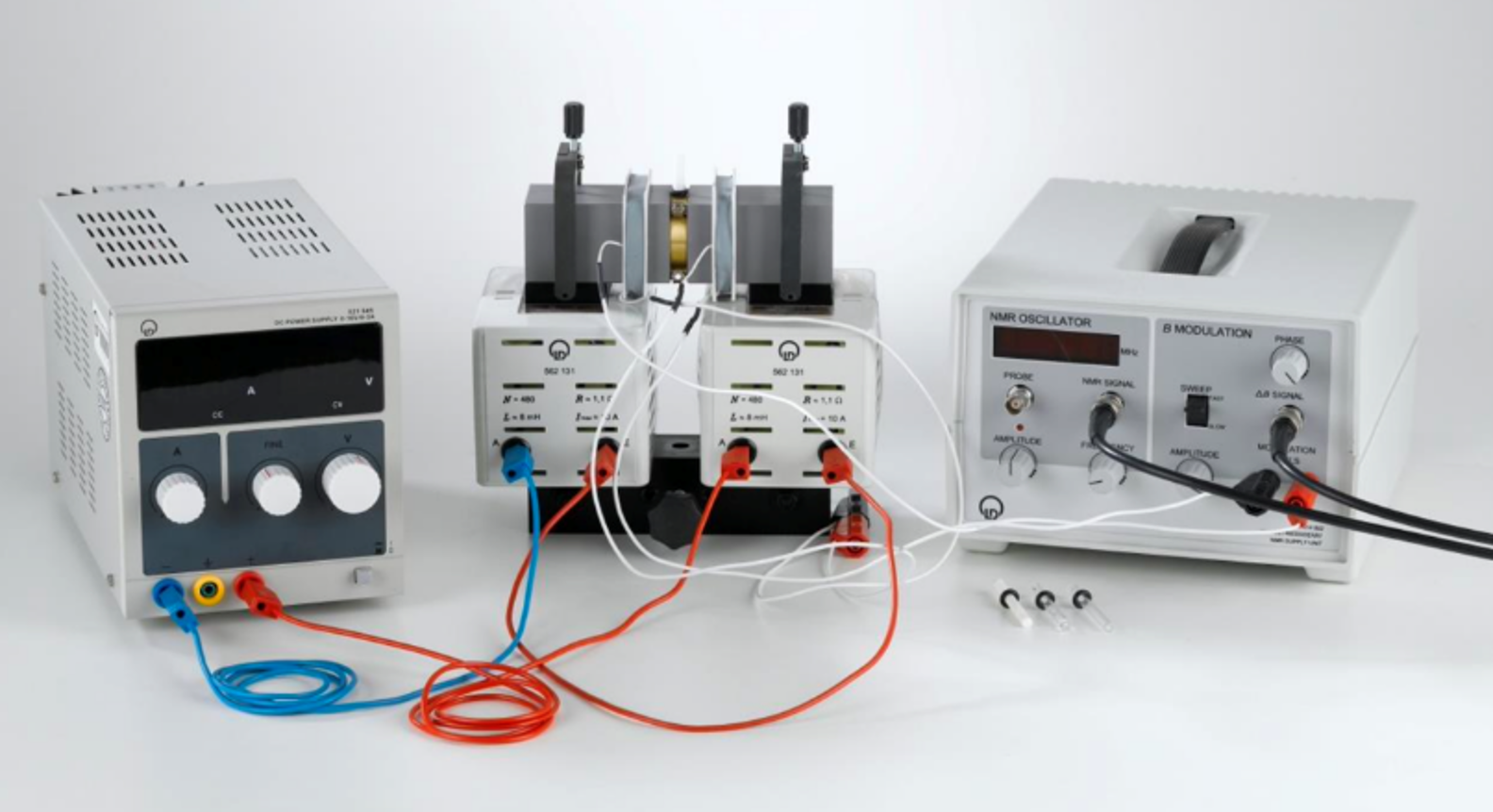
This project started with the setup out lined here. The device used was a Leybold-Didactic NMR device . The device is powered by a lab-standard programmable power supply. The device has two components, one Electronic and one Mechanical. The user sets the settings and operates the device with the electronic component. The mechanical system handles the magnetic signals and the material being tested. Overall, this device operates as a Continuous-Wave NMR or CW-NMR device.
Overview
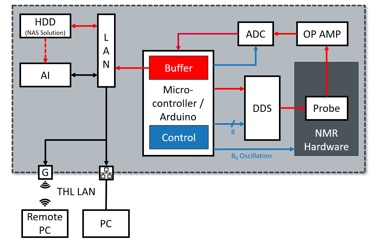
This initial device was then analyzed for its top-level components and very basic system identified. From this initial discovery, an initial architecture was described and requirements outlined for development. A key functional part this the microcontroller. This device sets the high frequency signal, sets the low frequency signal, sets the power output, accepts the digital return signal, and sends the digitized data to the land area network (LAN). The high frequency signal is generated by a direct digital synthesizer (DDS) module. The probe generates the analog signal. The analog-to-digital converter (ADC) converts this signal from digital to analog. The LAN handles the data between the hard drive disk (HDD) and the AI performing pattern recognition to identify material.
Sub Systems
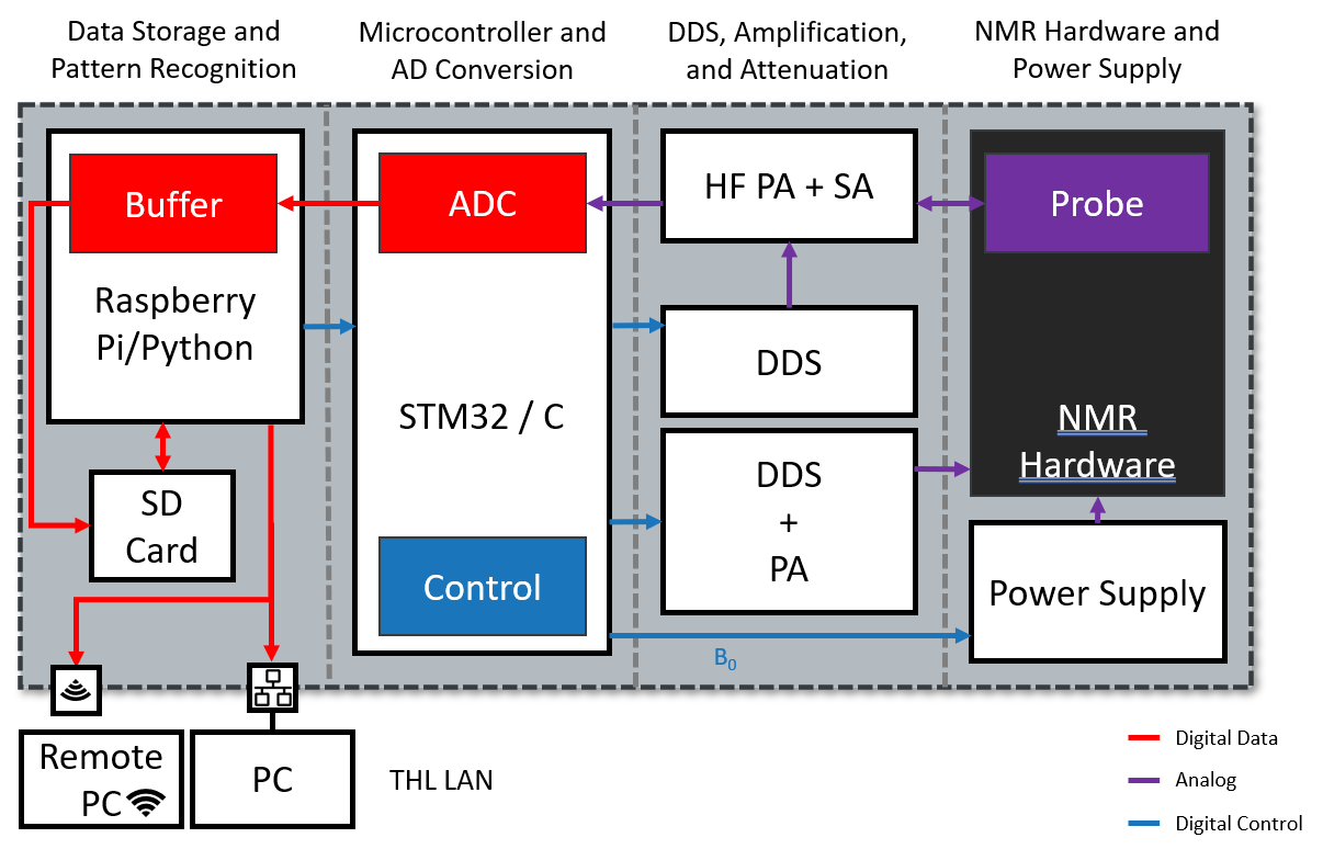
While I designed the system architecture and performed many of the tests for parts of the machine, other researchers and teams had responsibilities in other sections of the system. This meant that subsystem identification was important for clear project management between the different groups. Splitting the project along technical requirements yielded 4 subsystems: Data Storage and Pattern Recognition, Microcontroller and Analog-to-Digital Conversion, DDS/Amplification/Attenuation, and NMR Hardware and Power Supply. Each Sub System can be further described.
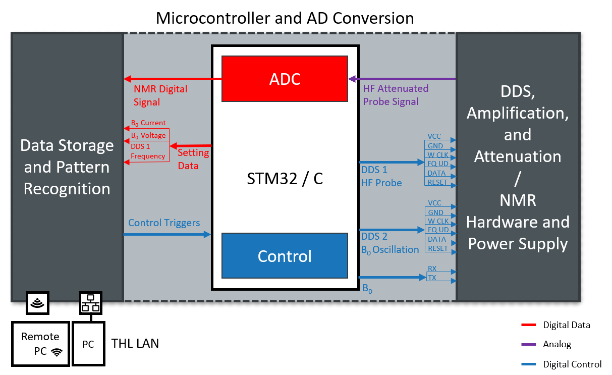
Microcontroller and Analog-to-Digital Conversion
Initially, an Arduino DUE wa selected as a Microcontroller for this system. It was quickly discovered that the onboard ADC was much too slow to collect useful data. The change was made to implement an STM32 that uses C to program much faster without unnecessary subroutines present in arduino. The DDS selected for this project ( the AD9850 ) was only able to create one sinusoidal signal, so a second DDS was added to the system. Further, the pattern recognition and downstream signal analysis need the settings data (high frequency rate, voltage and current from the low frequency circuit). The overall triggers from the user were also passed into the microcontroller.
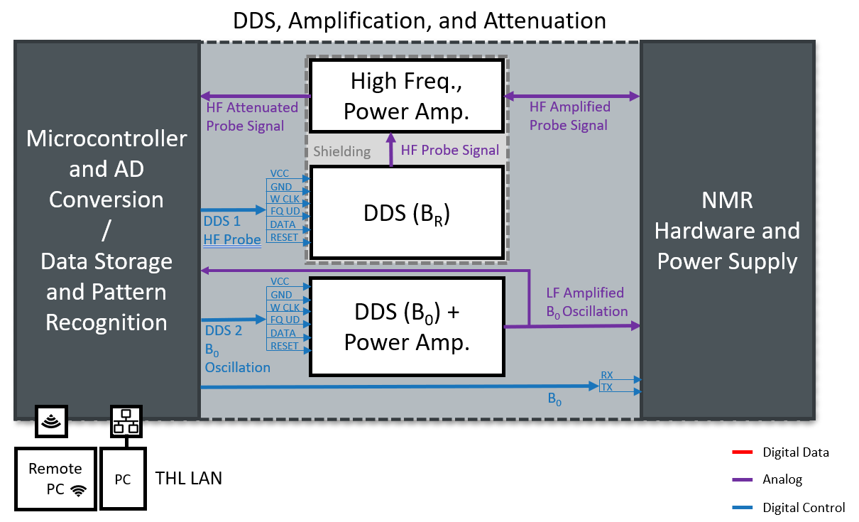
DDS/Amplification/Attenuation
This sub system was the most technically complicated, as high frequency electronics are much more difficult to prototype. It was ultimately deemed out of scope for this project to build this circuit, however the circuit itself was identified and the requirement set for later development by a more specialized researcher. The B0 (low frequency signal had to be amplified cleanly using a power amplifier. The high frequency signal coming from the probe needed to be attenuated before going to the ADC. Another complication to this system is the shielding necessary for the high frequency circuit. The circuit operates around 20-30 MHz, which is within the range of ambient radio signals. This is a common issue with many NMR devices and presents a technical challenge to overcome.
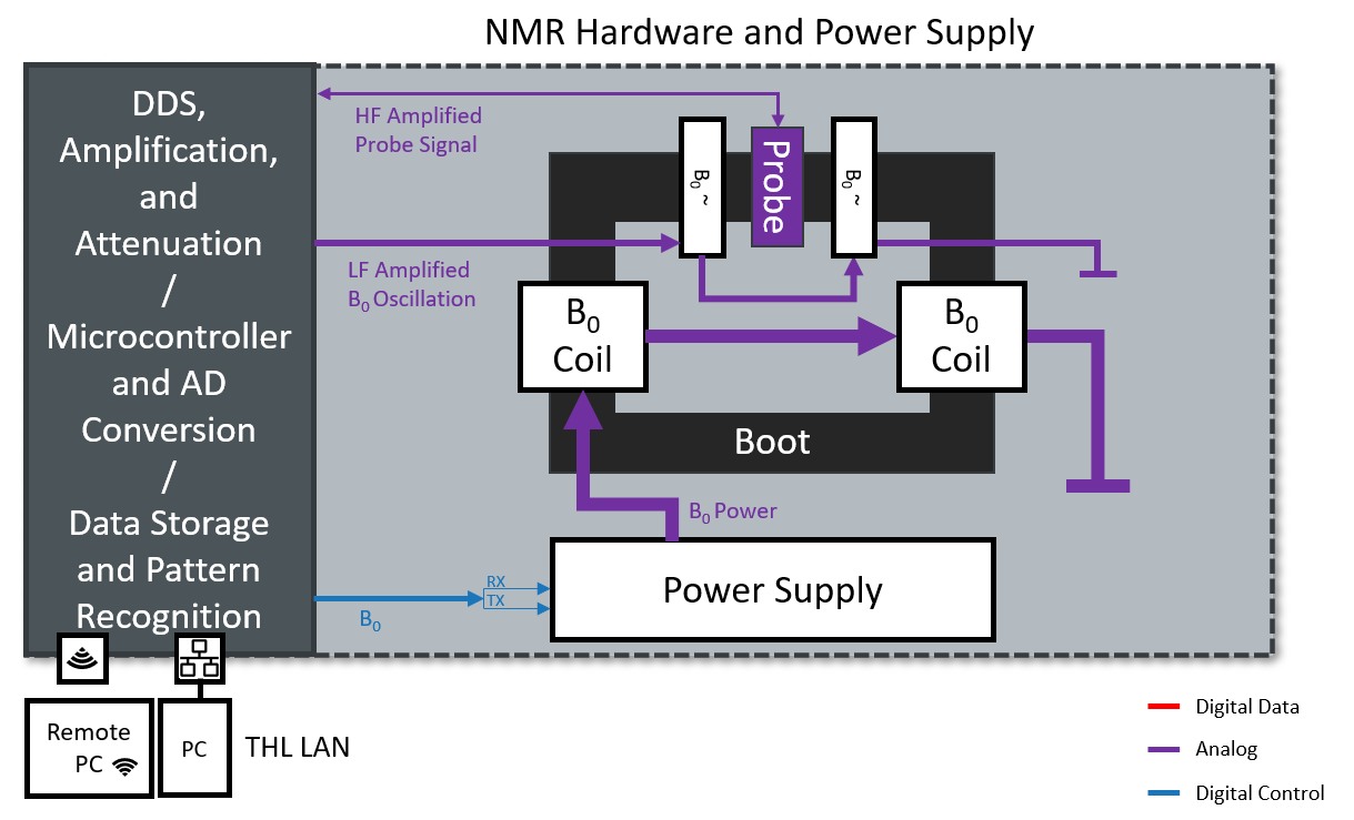
NMR Hardware and Power Supply
The power supply received signal to alter its settings, and powered the B0 circuit. The probe was electrically isolated from the B0 circuit and is only connected to the amplification and attenuation circuit from previous sub system. Finally, the field generated by the B0 coils, was altered by the smaller coils powered by the low frequency signal from the second DDS. This sub system was not altered from the starting point. A group is developing a new boot to propagate the magnetic field induced by the B0 circuit. For the sake of this project, it was sufficient to understand on an electrical basis how this system works and assist that team in their development by providing key requirements.
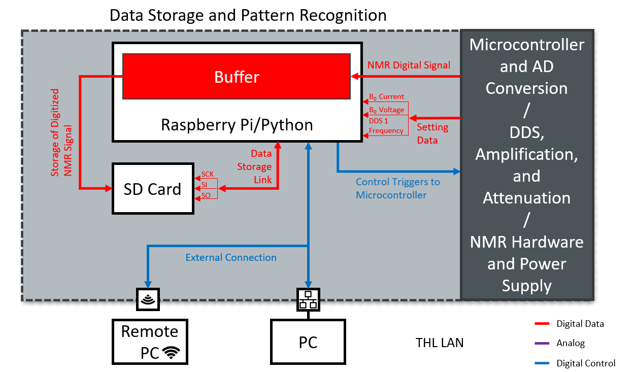
Data Storage and Pattern Recognition
Finally a Raspberry Pi was developed with a python kernel. This was done for 3 reasons: creating a user interface is easy in Python, AI frameworks are most commonly found in python, and the Raspberry pi removes cost but provides a fully functional computer. The data size was found to be small enough to fit hundred of samples onto a single SD card.

Next Steps
With the system architecture complete, future projects could be identified. Further developments were needed. Within the DDS/Amplification/Attenuation subsystem, all the components were prototyped seperately. A full integration of all the electronics is needed. For the Data Storage and Pattern Recognition subsystem, the Pattern Recognition (AI) system had to be developed now that the signal data is better known. Further integrating the communication pipeline between the STM32 and the Raspberry Pi and developing the user interface was another project to be completed.